Measuring, Metering Manifold
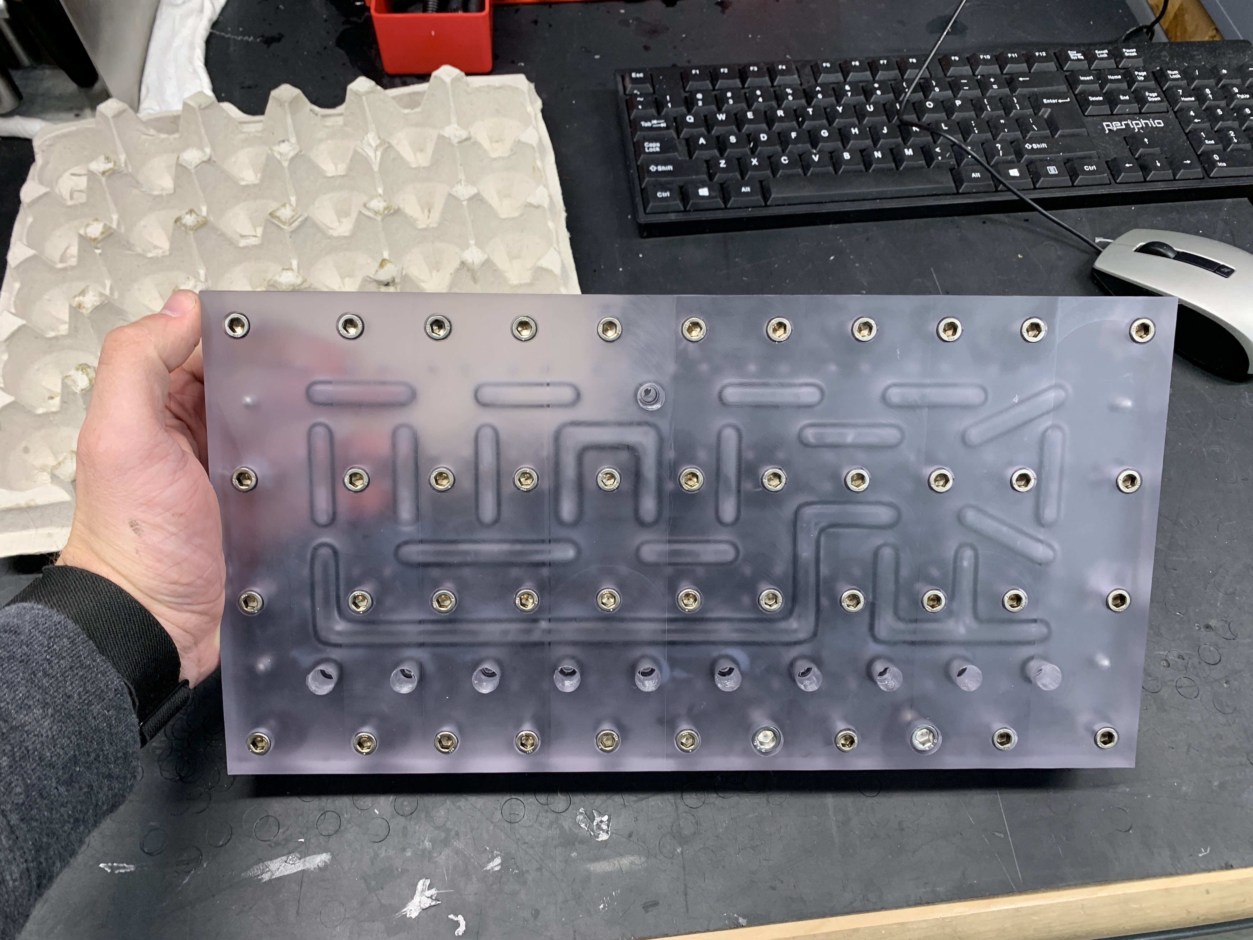
This is a fluidic manifold that I created in the machine shop with a fellow engineer at On Demand Pharmaceuticals.
Design
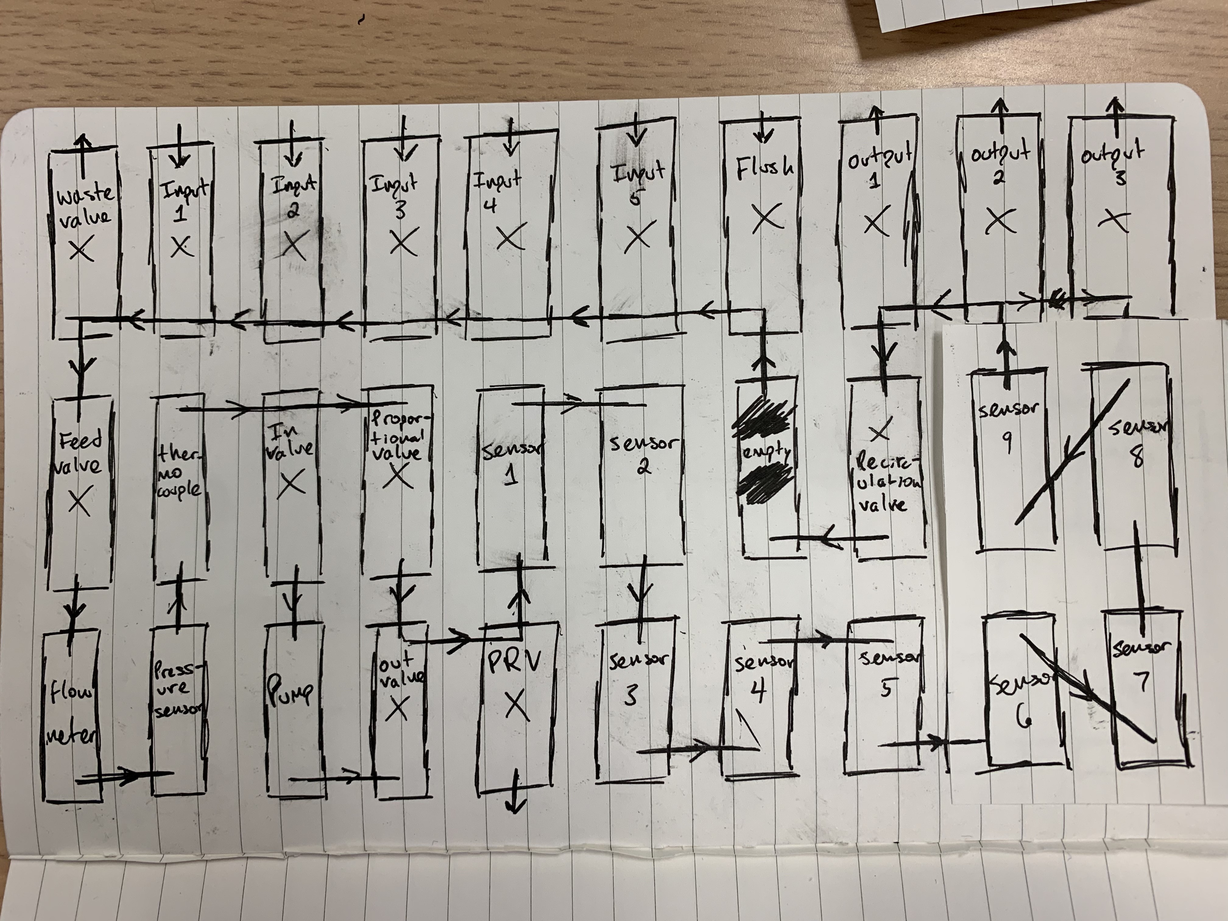
I spent hours hashing out the details of the fluid path, sensors, and features of the manifold. Below is an example of one of the block diagrams I made to represent the fluid path and measuring components on the manifold:
After all the brainstorming and design work was done, I modeled the manifold in Solidworks. The manifold’s design consists of two plates: a bottom plate that contains the fluid paths and o-ring grooves, and a top-plate that contains mounting positions for sensors and break-outs from the manifold. The manifold features an innovative concept in the form of “adapter blocks”. These adapters sit on top of the top plate, and can interface with different sensors, transducers, thread types, and tubing. A picture of an adapter block mounted with a solenoid valve on top of a prototype of the top plate can be seen below:
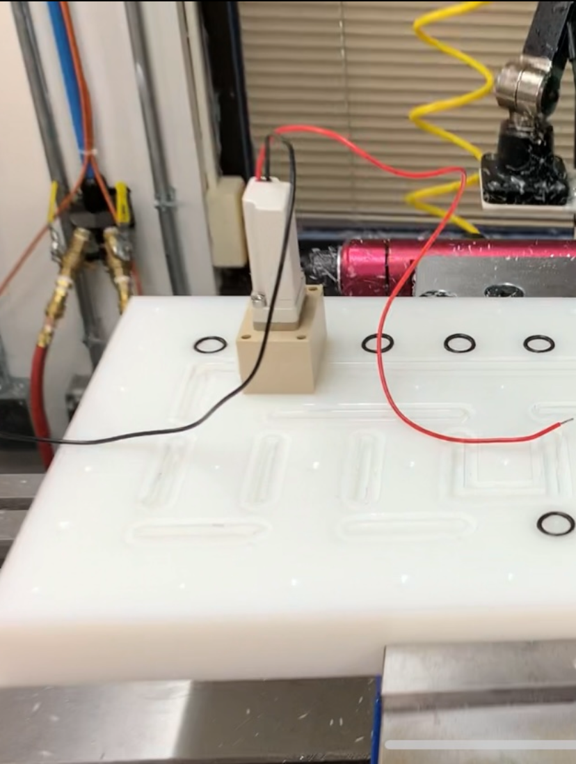
These adapters are extremely flexible, and have the ability to be machined to interface with any type of fluidic connection.
Prototype
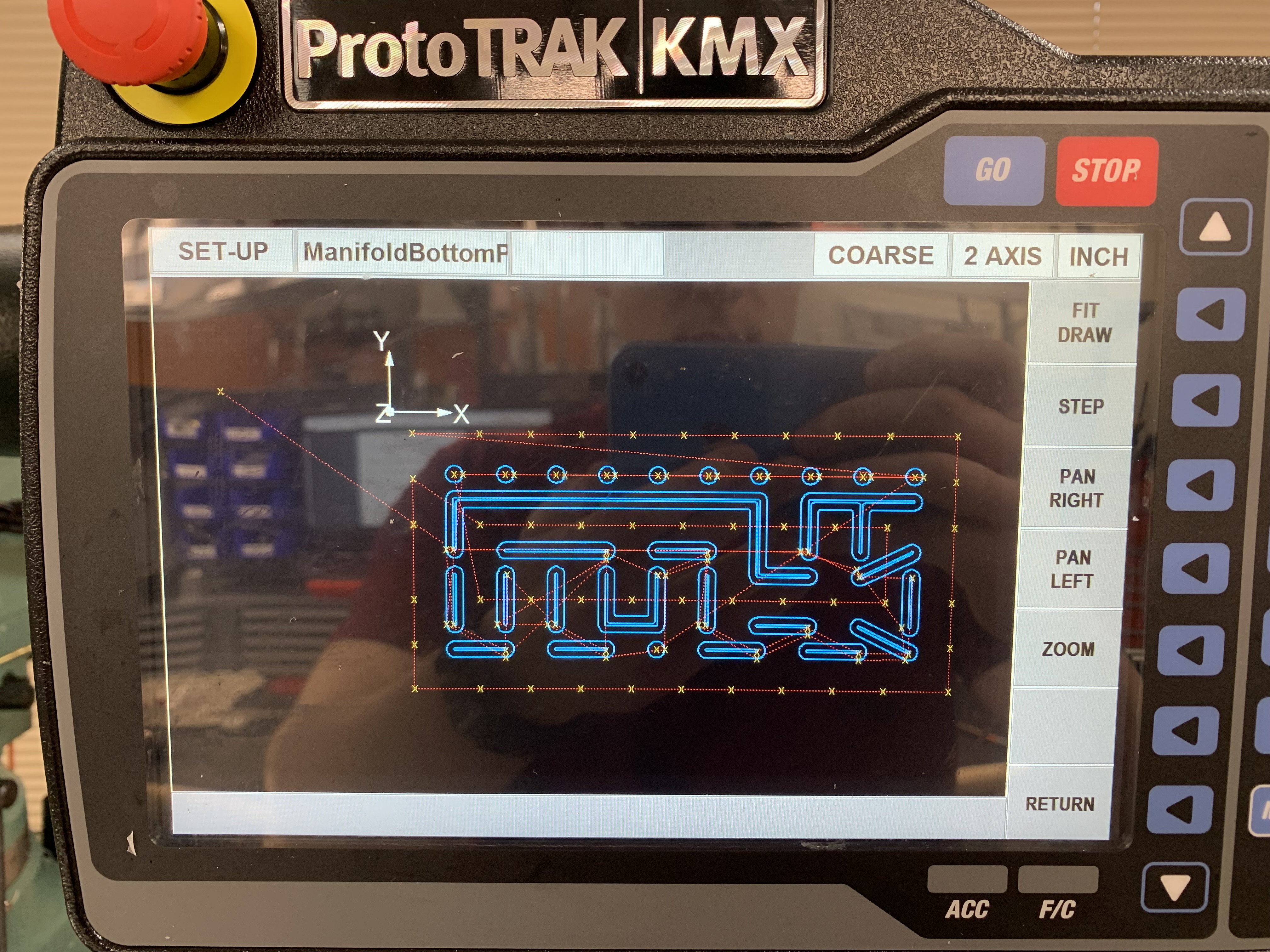
I leveraged this model to create pathing for our 2-axis mill. The mill was purchased with a proprietary software package that allowed me to create g-code from .dxf files. This made the numerous, complicated, and windy turns of the fluid path trivial to machine.
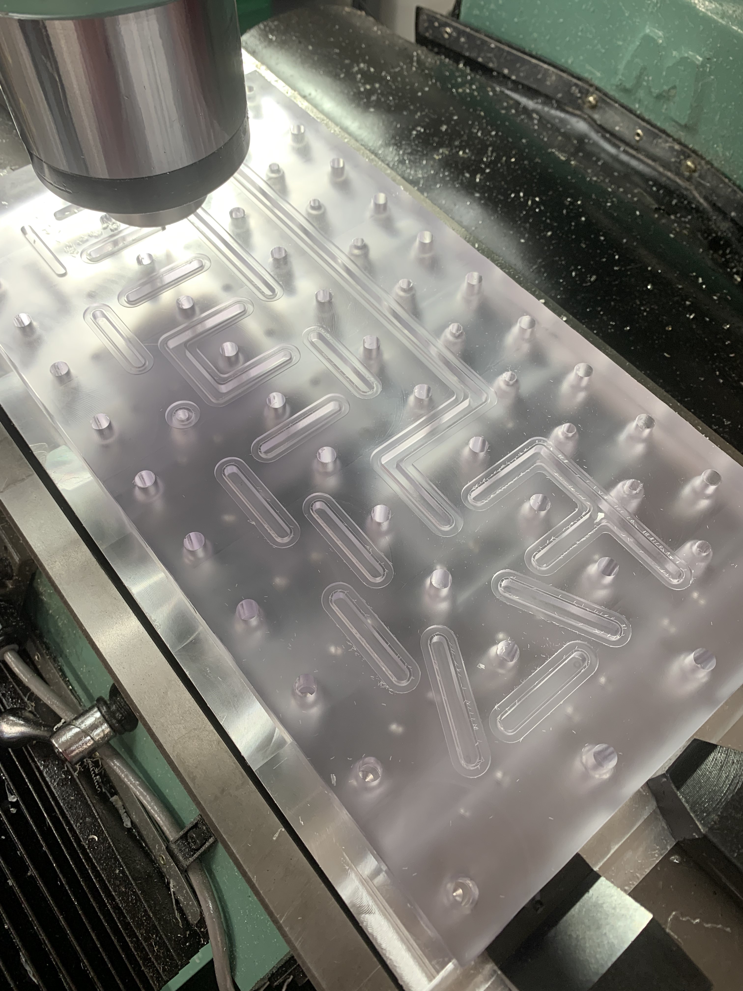
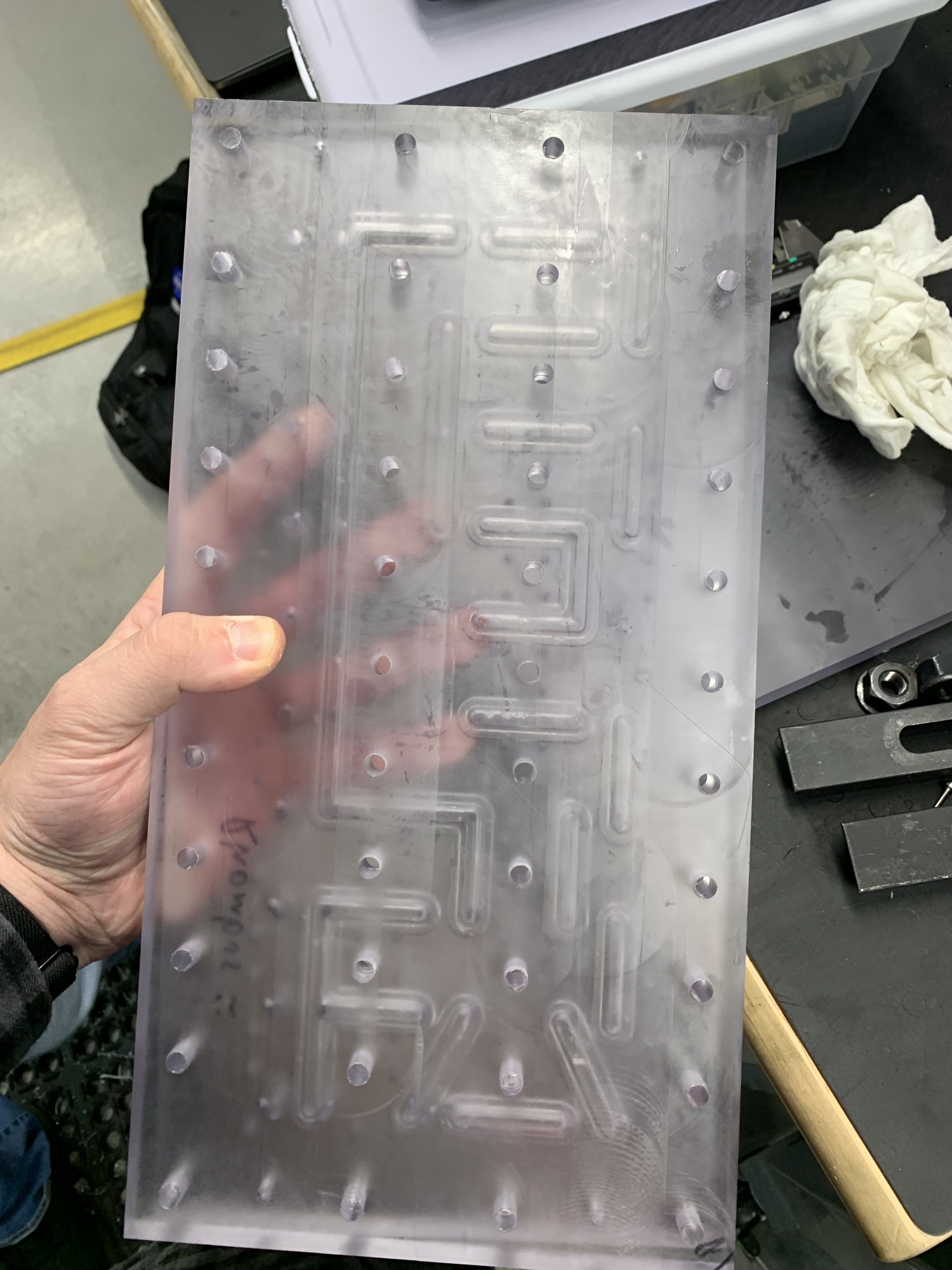
The idea of this project is to create a fluidic manifold capable of metering and measuring abrasive chemicals used in pharmaceutical production. It has five inputs, and three outputs, each of which are solenoid valves. Pinch valves could alternatively be used. There’s a waste valve to get rid of unwanted material, a pressure relief valve, a feed valve for controlling when fluids enter the main fluidic pathway, and a flush input for cleaning the fluidic pathway. The manifold has a flowmeter, thermocouple, and pressure transducer immediately after the feed valve to take initial measurements of the input fluid. To drive fluid flow there are two options: a break-out to a peristaltic pump, and a proportional valve to regulate pressure-driven flow. Immediately before the outputs are nine spots for various sensors. My idea was to leave room for extra sensors to boost flexibility. There also exists a recirculation valve for keeping the process fluid within the manifold for multiple iterations.
Finished Product
During the course of this project, I learned a ton about machining, mechanical design, and the engineering design process. This was the first time I have truly been able to implement the full mechanical design process myself, and it’s one of the most valuable experiences of my career. Thank you to ODP for the opportunity to contribute to our mission in a meaningful way while at the same time improving and developing my skills as an engineer.
Finished Product:

Youtube Videos of the Fabrication
Cutting the Fluid Path
Concept, Design, Prototype
Tapping Holes Using the Tap-o-matic
Measuring the Surface Finish Using a Dial Indicator