Feedforward Plus Feedback Control for Mobile Manipulation With the youBot
A python script that plans a trajectory for the end-effector of the youBot mobile manipulator.
Link to this project’s Github

Introduction
This python script uses the Modern Robotics library to plan a trajectory for the end-effector of the youBot mobile manipulator (a mobile base with four mecanum wheels and a 5R robot arm), performs odometry as the chassis moves, and performs feedback control to drive the youBot to pick up a block at a specified location, carry it to a desired location, and put it down.
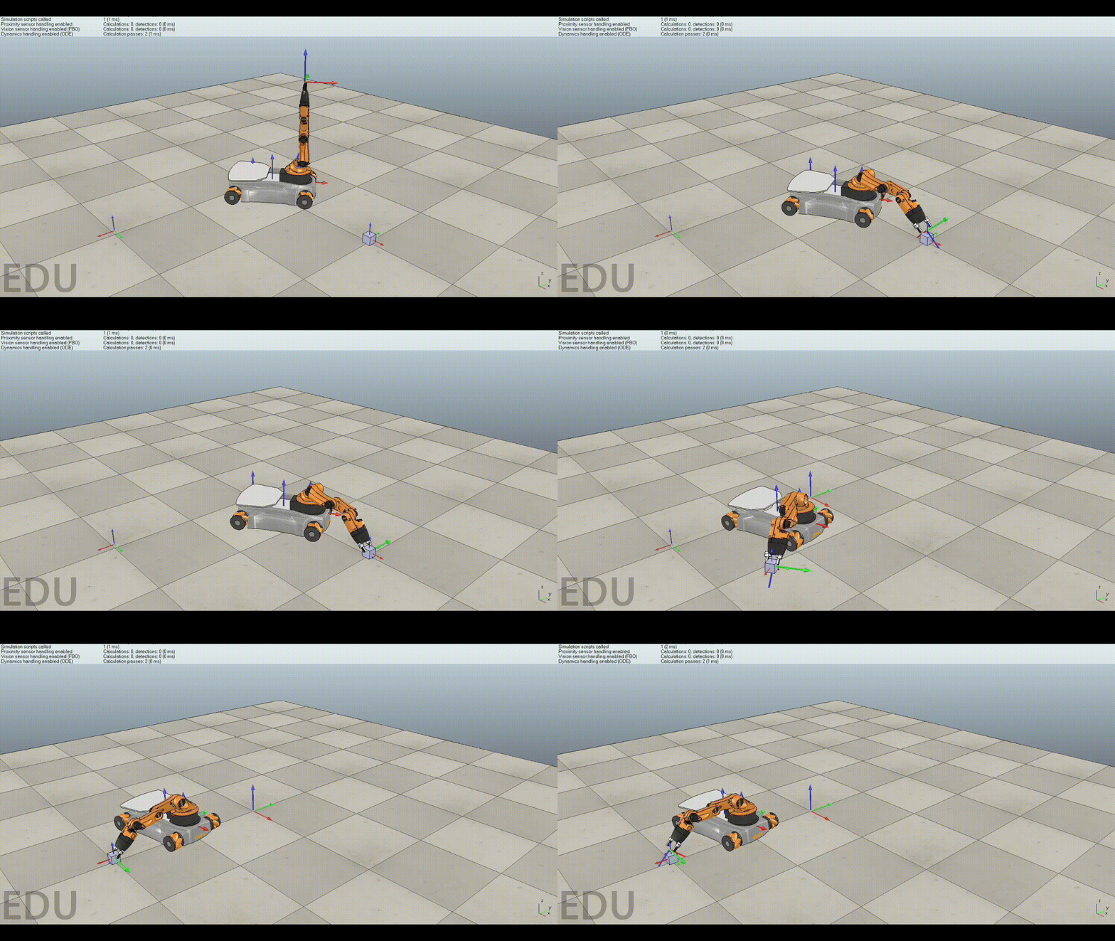
The final output of the script is a csv text file that specifies the configurations of the youBot chassis, the angles of the four wheels, the joint angles of the 5R robot arm, and the state of the gripper (open or closed) as a function of time. This specification can then be “played” using the CoppeliaSim simulator.
How to Run
CoppeliaSim can be installed here, and the necessary scenes for “playing” the csv files can be downloaded here.
In the terminal, navigate to the trajectory_generation.py file inside the /code/ directory of this repository. To run the file, execute the following command:
python3 trajectory_generation.py
The csv file generated will be called trajectory.csv
Open CoppeliaSim, and open the file named Scene6_youBot_cube.ttt. Click the play button, and then type in the path to trajectory.csv into the popup box.
Implementation
The code here drives the youBot to successfully pick up a block and put it down at a desired location. To do this, I employed automated planning and control techniques from the Modern Robotics textbook.
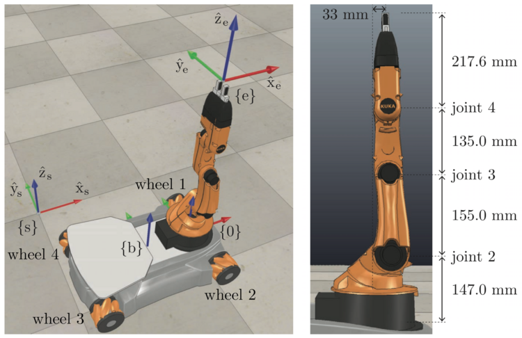
The image below illustrate the youBot at its home configuration:

In this project, we assuume no joint limits on the five joints of the robot arm.
A trajectory for the youBot is made up of thirteen elements. These thirteen elements are:
- Chassis \(\phi\)
- Chassis x
- Chassis y
- Joint 1 \(\theta\)
- Joint 2 \(\theta\)
- Joint 3 \(\theta\)
- Joint 4 \(\theta\)
- Joint 5 \(\theta\)
- Wheel 1 \(\theta\)
- Wheel 2 \(\theta\)
- Wheel 3 \(\theta\)
- Wheel 4 \(\theta\)
- Gripper State (0 for open, 1 for closed)
The total robot trajectory consists of the following eight trajectories:
- A trajectory to move the gripper from its initial configuration to a “standoff” configuration a few cm above the block.
- A trajectory to move the gripper down to the grasp position.
- Closing of the gripper.
- A trajectory to move the gripper back up to the “standoff” configuration.
- A trajectory to move the gripper to a “standoff” configuration above the final configuration.
- A trajectory to move the gripper to the final configuration of the object.
- Opening of the gripper.
- A trajectory to move the gripper back to the “standoff” configuration.
There are three functions that make up the core of the trajectory generation script:
NextState()
- Inputs
- current_configuration: The current configuration of the robot
- speed_controls: The current angular velocities of the wheels and robot joints.
- \(\Delta t\): The time step from the current configuration to the next configuration.
- max_angular_velocity (\(\dot{\omega}_{max}\)): The max angular velocity of either the wheels or the robot joints.
- Outputs
- new_configuration: The new robot configuration after \(\Delta t\) has passed.
The NextState() function should generate a new robot configuration based on a robot configuration at t-1, an array of velocities of the chassis wheels and robot arm joints, and a time step.
TrajectoryGeneration()
- Inputs
- TseInitial: The initial configuration of the end-effector in the reference trajectory.
- TscInitial: The cube’s initial configuration.
- TscFinal: The cube’s desired final configuration.
- TceGrasp: The end-effector’s configuration relative to the cube when it is grasping the cube.
- TceStandoff: The end-effector’s standoff configuration above the cube, before and after grasping, relative to the cube.
- k: The number of trajectory reference configurations per 0.01 seconds.
- Outputs
- output_trajectories: An length N list of trajectories
The purpose of the TrajectoryGeneration() function is the generate reference trajectories for the feedforward feedback controller to compare itself to. It will generate an ideal trajectory for the robot end-effector to follow as it moves between the eight desired states of the total robot trajectory.
FeedbackControl()
- Inputs
- X: The current actual end-effector configuration.
- Xd: The current end-effector reference configuration.
- Xdnext: The current end-effector reference configuration future time dt.
- Kp: The proportional gain.
- Ki: The integral gain.
- \(\Delta t\): The timestep.
- integral error: The cumulative integral error
- Outputs
- V: The desired end-effector twist
- integral_error: The cumulative integral error
- xerr: The error twist that takes X to Xd in unit time
The FeedbackControl() function controls the feedforward plus feedback control law in task space. This function can be represented mathematically as follows:
\(\mathcal{V}(t) = [Ad_{\mathcal {X}^{-1}X_d}]\mathcal{V_d}(t) + K_pX_{err}(t) + K_i\int_0^tX_{err}dt\)